When a ground plane is connected to the power supply only at a single point, the entire ground plane will be held at nearly the same potential. The ground return to the power supply should also be connected to a ground plane at a single point.

This minimizes any potential differential between PCB traces ground plane connections by simply reducing the distance between them. Rather than connecting ground connections at different points, it is better to route traces to a ground connection with the ground plane. While PCB ground ring that arises due to a ground loop can never be completely eliminated, it can be significantly reduced such that its effects on signal integrity are minimized. Proper planning can mitigate several potential PCB ground loop problems PCB ground loop and return path potentials tend to be on the order of microvolts, but this is still enough to cause signal integrity problems, especially in low current devices. This is a major source of PCB ground loops in the ground plane. If two signal traces connect to the ground plane at different points, a small voltage differential can exist between these two connections. No ground plane is a perfect conductor it has some resistance and reactance. This should illustrate the convenience of using a large ground plane to route return signals rather than routing return traces individually.

When the ground plane is placed directly below the plane containing your signal traces, all of your signal traces will induce their own return path directly in the ground plane. By placing a ground plane below signal traces, the return signal will naturally form below the signal trace and your circuit will be complete. Placing a signal trace closer to its ground plane will ensure lower loop inductance, which helps reduce susceptibility to EMI. This means that if you want to ensure a reliable return signal to ground, your signal and return should be placed as close together as possible. So why is this important? If the trace is closer to the ground plane, the capacitive impedance seen by a signal on a trace will be lower, which forces the return path to follow closer to the area beneath the trace. If we briefly consider a trace and its ground plane in isolation, current is induced in the ground plane through the parasitic capacitance between the trace and its ground plane. The strength of the induced return current depends on a number of factors.
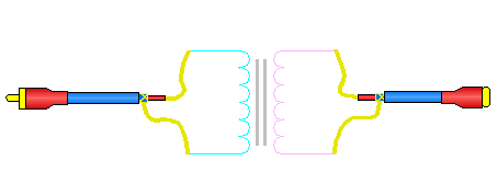
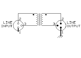
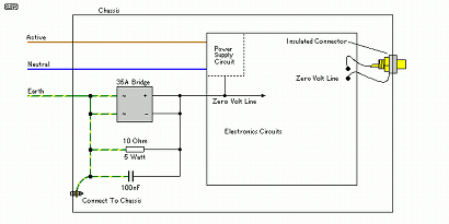
Ground loop isolator schematic full#
As the signal rises to full strength and moves through the board, the signal and return traces create a current loop. In a PCB layout, signals are routed around the board using signal and nearby return traces. If you remember your Electronics 101 class, you know that all electric currents move around closed loops. Read on to find out about preventing PCB ground loops. Ringing or humming sounds in some audio systems are just one manifestation of PCB ground ring. Large currents can exist in ground planes, and a voltage differential between ground connections causes the formation of a ground loop. Ground loop PCBs generate noise in electric circuits, sometimes called a ground ring. In reality, PCB ground loops that form due to shoddy design are the source of the problem. What components are to be considered a problem? The decoupling capacitor or ground wire? How about the bypass capacitor or PCB ground loop design interference? The stereo manufacturer will blame the component manufacturer and the component manufacturer can’t blame anyone. When you take it back to the store the clerk blames the manufacturer. You buy that awesome stereo system only to hear that familiar humming sound in the background. The fancy Monster cables are in the trash bin and older RCA cables from 80's are doing a great job.I think we’ve all been there. but changing the sound card output from single-ended to balanced, with an active circuit, might have the same noise. Is there a decent ground loop insulator, with >12kohm impedances, that doesn't break the bank? I am looking at bandwidth but mostly distortions.Īlternately my amp has balanced inputs. But then, I am unhappy of having a transformer adding distortion between the two.

I have a cheap ground loop isolator and, with that in circuit, there is complete silence. touched a wire between the cases, still noise. I connected both to the same power strip. Probably because I have an UPS, I don't know. Not hum, but something that's something else. To my unpleasant surprise, when they are connected them with RCA cables I can hear some low level electrical noise.
Ground loop isolator schematic Pc#
I have bought a headphone amplifier and I connected it to my PC sound card (SoundBlaster ZxR).


 0 kommentar(er)
